Leave A Message
If you are interested in our products and want to know more details,please leave a message here,we will reply you as soon as we can.


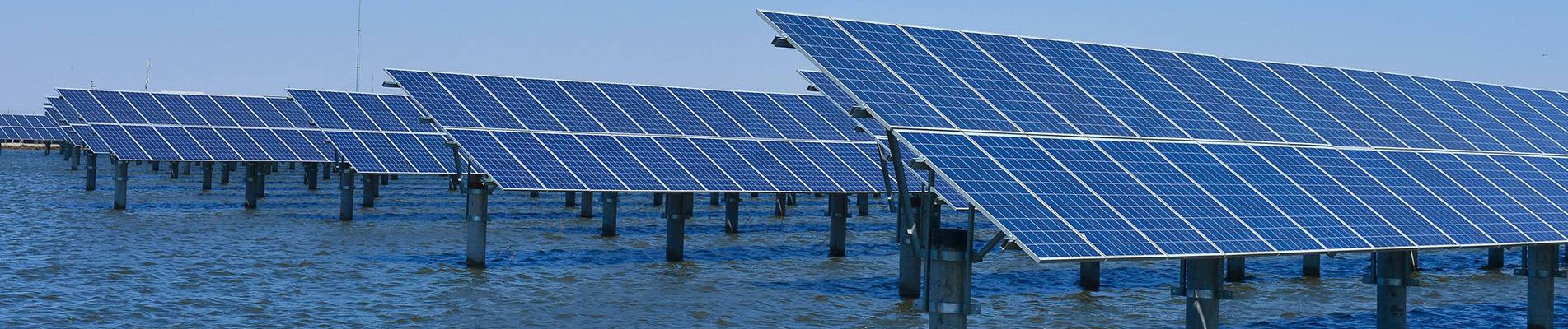
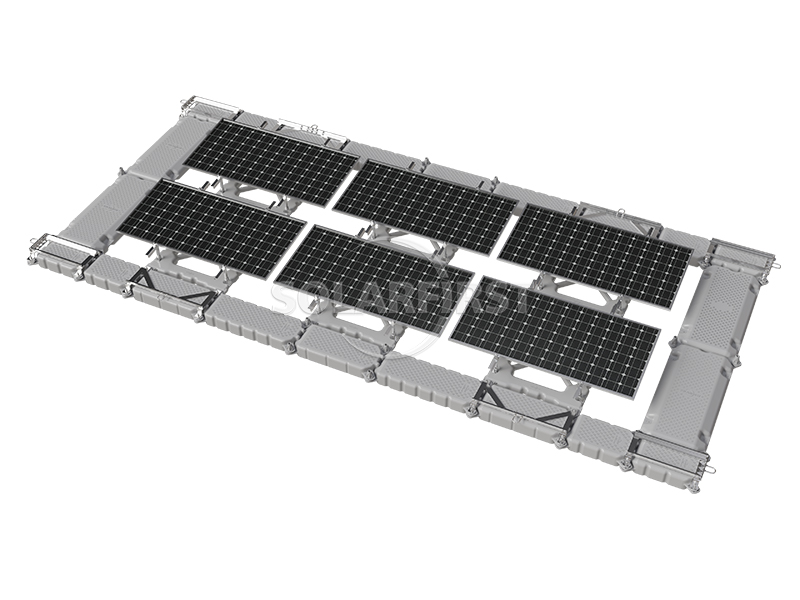
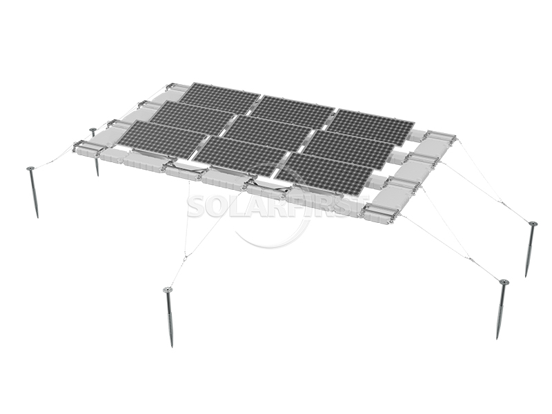
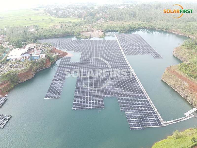
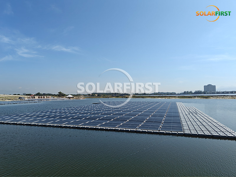
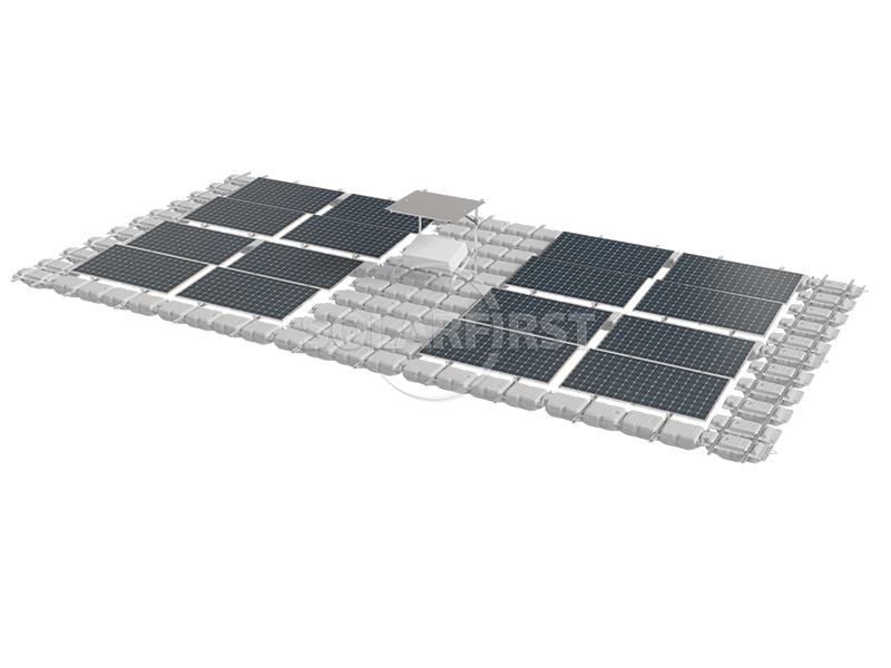
The TGW02 series floating photovoltaic system is primarily designed for floating photovoltaic power station applications, using a modular floating structure to support photovoltaic modules. The system's design balances installation efficiency with adaptability to different water environments, making it suitable for lakes, reservoirs, mines, and some near-shore areas. Its overall flexible connection helps mitigate the impact of water surface fluctuations on the structure, providing a feasible floating solution for photovoltaic projects of varying sizes.
Product Description
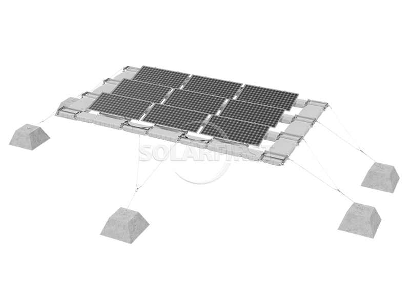
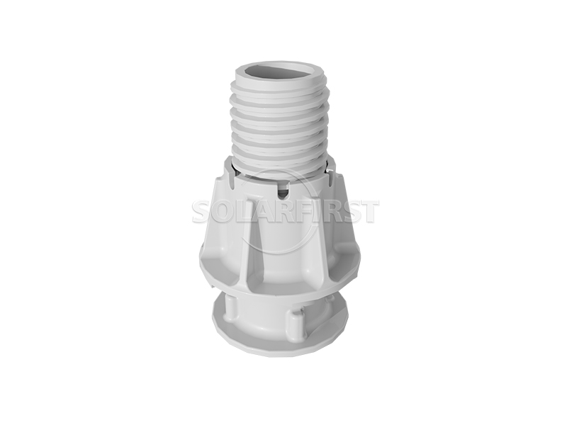
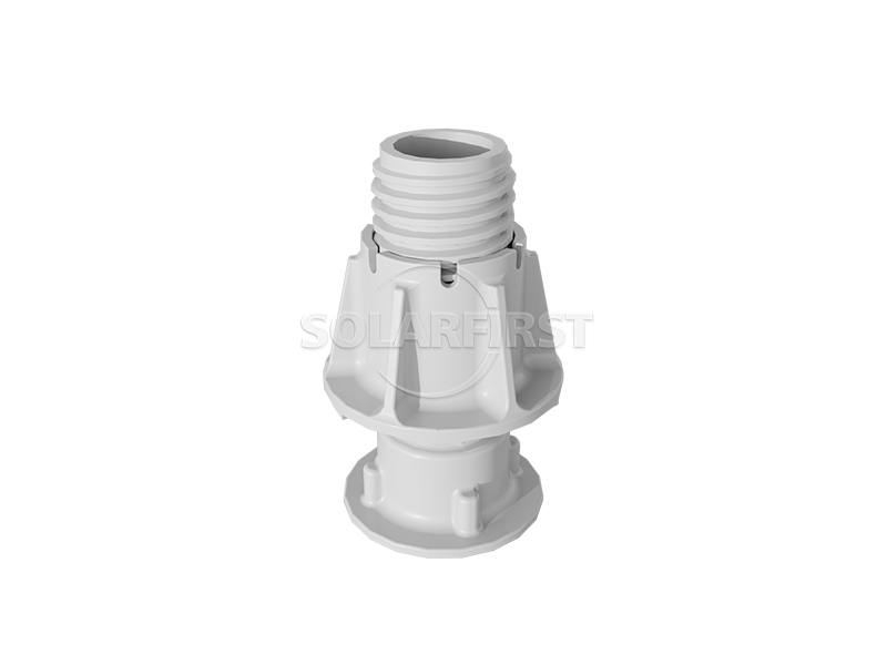
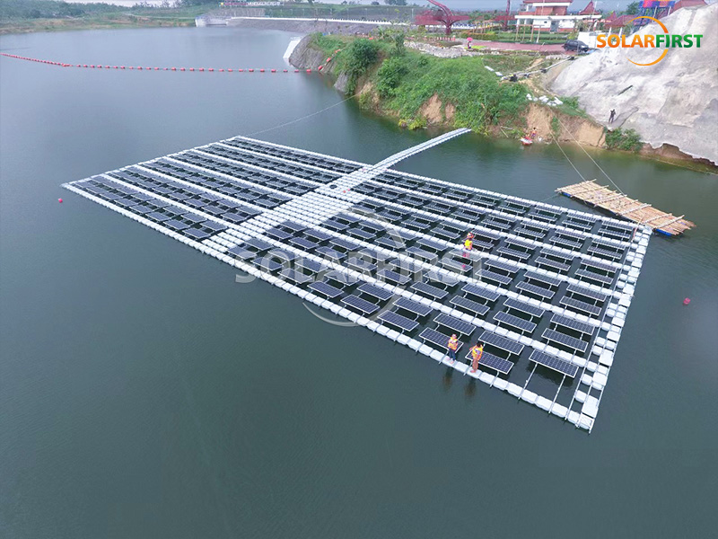
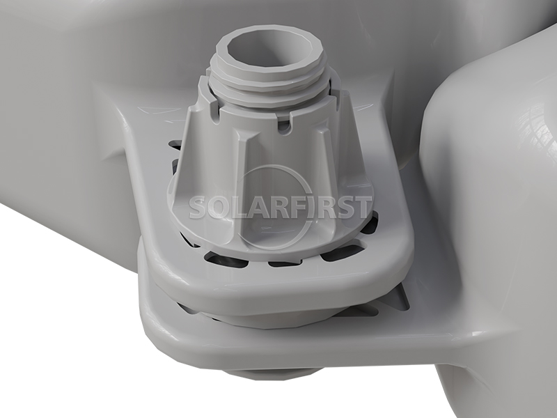
The TGW02 series floating photovoltaic system uses a main float positioned beneath each individual module as its basic unit, resulting in relatively uniform buoyancy distribution. The maintenance access channel is at least 425mm wide, providing ample walking space for daily inspections. Plastic bolts connect the channels, giving the array a degree of flexibility to adapt to water level changes and wave disturbances. For electrical cabling, cable channels can be flexibly arranged in north-south or east-west directions to accommodate different power station layouts. The anchoring system supports various methods, including shore-side pile anchors, concrete block anchors, and underwater pile anchors, allowing selection based on the specific geological conditions of the water area.
Anchoring System
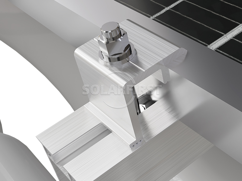
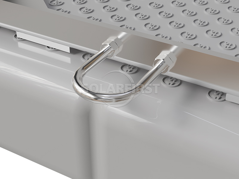
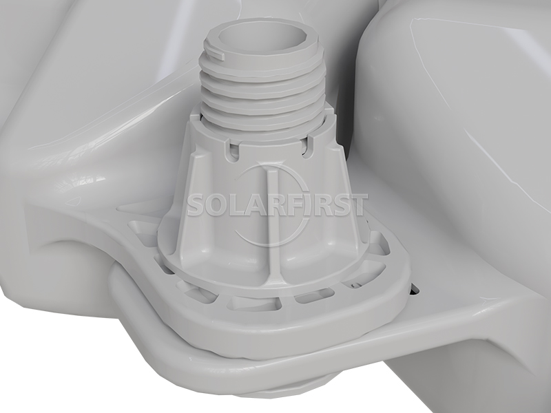
Product Components

Advantage
▪ Installation Efficiency: Fewer front and rear support structural components and fewer fastening bolts result in a relatively streamlined construction process.
▪ Flexible Layout: Adjustable component spacing accommodates angle requirements at different latitudes; the layout can follow natural terrain, facilitating increased installation density.
▪ Safe Movement: Maintenance access width ≥ 425mm provides basic protection for personnel passage.
▪ Float Adaptability: The flexible structure with plastic bolt connections can deform to some extent with water surface fluctuations, reducing the risk of rigid damage.
▪ Floating Body Strength: SGS testing showed no significant damage or deformation of the overall structure under 42m/s wind speed conditions, meeting common wind load requirements.
▪ Convenient Cabling: Cable routing can be flexibly selected (north-south or east-west) to adapt to diverse layouts.
▪ Multiple Anchoring Options: Three anchoring methods are provided for different water geological conditions, facilitating project adaptation.
Parameters
| Installation | Water Surface |
| Anchoring Methods | Onshore pile anchors/underwater pile anchors/concrete block anchors |
| Sueface Wave Height | ≤0.5m |
| Sueface Flow Rate | ≤0.5m/s |
| Wind Load | up to 60m/s |
| Snow Load | 0.5kn/m² |
| Tilt Angle | 5°, 10°, 15° |
| Standards | GB50009-2012, EN1990: 2002, ASCE7-05/ASCE7-10, AS/NZS1170, JIS C8955: 2017 |
| Material | HDPE, Anodized Aluminum AL6005-T5, Stainless Steel SUS304 |
| Warranty | 10 Years Warranty |
Applicable Scenarios
▪ Inland lakes and reservoirs
▪ Aquaculture ponds (solar-fishery complementary)
▪ Mining pits in coal mining subsidence areas
▪ Oxidation ponds at wastewater treatment plants
▪ Saline-alkali land or saline-alkali water areas
▪ Nearshore areas (corrosion conditions need to be assessed)
Important Notes:
▪ The anchoring method must be designed and selected by professionals based on the specific water depth, bottom sediment, and current velocity conditions.
▪ For use in nearshore or high-salt-spray environments, it is recommended to additionally evaluate the corrosion protection measures for metal connectors and bolts.
▪ The loosening of plastic bolt connections under long-term wave action should be included in regular inspection items.
▪ When the surface of the float is slippery, necessary anti-slip measures must still be taken.
▪ The final setting of component spacing and angles should be verified in conjunction with the actual irradiance and latitude conditions of the project site.
Summary
This floating system uses a main float with flexible connections as its core structure, providing various angle, arrangement, and anchoring options while ensuring basic buoyancy and personnel passage width. Its installation process is relatively simple and it is adaptable to complex aquatic terrain. Third-party verified wind load capacity makes it a viable application reference in areas with normal wind speeds. Overall, the system is suitable for various non-extreme aquatic environments and can serve as a reliable technical solution for floating photovoltaic projects.
Solar First Project Reference
Related Knowledge Points
The TGW03 series floating photovoltaic system adopts a combination design of high-density polyethylene (HDPE) floats and adjustable metal supports, making it suitable for lakes, reservoirs, coal mining subsidence areas, and other water bodies. The system supports installation tilt angle adjustment from 0° to 15° and is equipped with hinged connectors and various anchoring solutions (onshore pile anchors, underwater pile anchors, concrete block anchors, etc.), enabling relatively stable operation under different hydrological conditions. The width of the maintenance access channel and the buoyancy per unit area are designed according to safety requirements, facilitating later inspection and maintenance.
Read More
The TGW02 series floating photovoltaic system is primarily designed for floating photovoltaic power station applications, using a modular floating structure to support photovoltaic modules. The system's design balances installation efficiency with adaptability to different water environments, making it suitable for lakes, reservoirs, mines, and some near-shore areas. Its overall flexible connection helps mitigate the impact of water surface fluctuations on the structure, providing a feasible floating solution for photovoltaic projects of varying sizes.
Read More
 en
en fr
fr de
de zh-CN
zh-CN ru
ru es
es pt
pt ja
ja ko
ko ar
ar